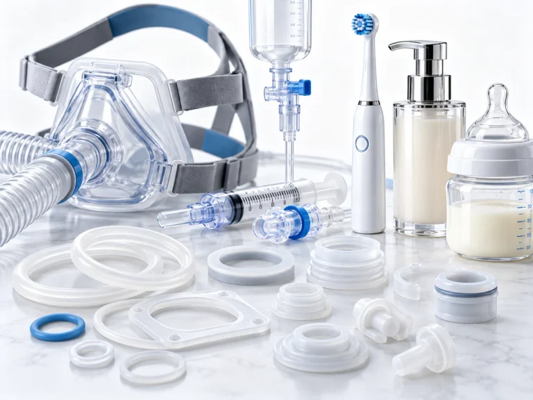
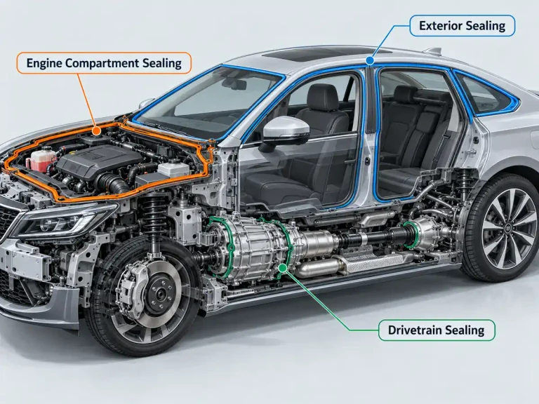
Liquid silicone rubber has become the material of choice for manufacturers producing medical devices, automotive seals, infant care products, and wearable electronics that demand biocompatibility, thermal stability, and precision. As adoption grows, engineering teams are discovering that the success of an LSR part depends far less on the material itself and far more on how the mold is engineered around it. A mold designed for standard thermoset rubber or thermoplastics simply does not translate well to LSR, and the gap between a mediocre mold and an excellent one shows up directly in scrap rates, cycle times, and part consistency.
The short answer is that a well-engineered LSR injection mold hinges on three interconnected systems: a cold runner network that delivers material without premature curing, a venting strategy that eliminates trapped air before it becomes a visible defect, and flash control measures that keep parting lines clean without secondary trimming. Get these three elements right and the rest of the process, from injection pressure to cycle time, tends to fall into place. Get them wrong and no amount of process tuning downstream will fully compensate.
The sections below walk through each of these design pillars in detail, along with the supporting decisions that determine whether an LSR tool performs reliably at production volume.
What Makes LSR Injection Mold Design Different from Standard Rubber Molding
LSR mold design differs from standard rubber or thermoplastic molding primarily because of the material’s ultra-low viscosity and rapid, heat-activated cure. These two properties change nearly every tolerance, clearance, and flow calculation an engineer would normally rely on for other elastomers.
Material Behavior and Flow Characteristics
Liquid silicone rubber behaves closer to a thin fluid than a solid pellet feedstock. Before curing, its viscosity can be similar to honey, which means it will find and exploit any gap in a mold that a more viscous material would never reach. This has several direct design consequences:
- Parting lines must be held to extremely tight tolerances, often under 0.02 mm, to prevent flash formation
- Vent channels need to be sized precisely, since a vent large enough to release trapped air can just as easily become a flash escape path
- Mold steel finish and hardness must resist the abrasive, low-friction flow of uncured LSR over thousands of cycles
Because the material cures through a platinum-catalyzed addition reaction triggered by heat, the mold itself functions as a chemical reactor. Temperature uniformity across the cavity surface is not a convenience; it is a requirement for consistent cure state and mechanical properties in the finished part.
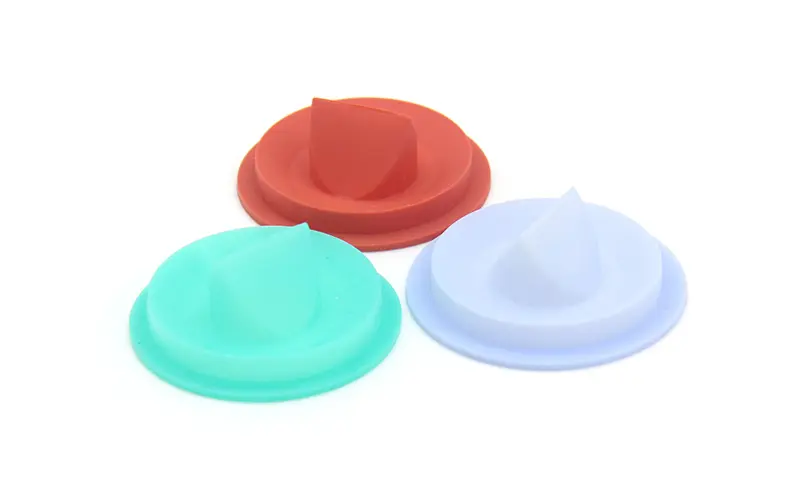
Engineers moving from thermoplastic tooling to LSR programs often underestimate how much the low viscosity changes basic assumptions about clearance. A gap between a core pin and cavity wall that would be perfectly acceptable for polypropylene or nylon can allow measurable flash on an LSR part, simply because the uncured material behaves more like a liquid than a molten solid. This is why LSR mold components are frequently held to tolerances an order of magnitude tighter than comparable thermoplastic tooling, and why mold steel selection tends to favor hardened alloys capable of maintaining that precision across long production runs.
Precision Tolerance Requirements
Applications like Silicone medical part production often carry tolerance requirements tighter than ISO 3302-1 Class M2, particularly for components such as seals, valves, and drug-delivery interfaces. Achieving this level of precision requires mold makers to account for LSR’s post-cure shrinkage, which typically falls between 2 and 3 percent depending on formulation, and to compensate for it in the original cavity dimensions rather than relying on secondary machining.
Cold Runner System Design for LSR Molds
A cold runner system keeps the LSR material below its curing temperature as it travels from the injection unit to the cavity, curing only once it reaches the heated mold cavity itself. This separation between the runner and cavity temperatures is the defining feature that distinguishes LSR tooling from standard thermoset processing.
Cold Runner vs Hot Runner Comparison
Some LSR processors evaluate hot runner or insulated runner alternatives, particularly for high-cavitation tools. The table below summarizes how the two primary approaches compare across the factors that matter most in production.
| Factor | Cold Runner System | Hot Runner (Insulated) System |
|---|---|---|
| Material waste | Higher, since sprues and runners are typically scrapped or reprocessed | Minimal, since material stays fluid within the manifold |
| Cycle time | Slightly longer due to runner cooling and part separation | Shorter, since no runner solidification step is needed |
| Tooling cost | Lower upfront investment | Higher due to manifold and temperature-zone complexity |
| Process control complexity | Moderate, with fewer temperature zones to manage | High, requiring precise zone-by-zone thermal control |
| Best suited for | Low to mid cavitation, cost-sensitive programs | High cavitation, high-volume production runs |
| Risk of premature cure | Lower | Higher if manifold temperature drifts |
For most LSR injection mold belows 16 cavities, cold runner systems remain the more practical and economical choice, offering reliable performance without the added engineering burden of manifold thermal management.
Key Design Parameters for Cold Runner Blocks
A cold runner block must maintain a temperature differential of roughly 15 to 20 degrees Celsius below the cavity temperature to prevent the material from beginning to cure inside the feed system. Achieving this consistently requires:
- Dedicated cooling channels routed independently from the cavity heating circuit
- Insulation plates or air gaps separating the cold runner plate from the heated cavity plate
- Polished, low-friction runner surfaces to minimize shear heating as material passes through
- Balanced runner geometry so that all cavities in a multi-cavity tool fill simultaneously
Runner diameter also matters more than many designers expect. Oversized runners increase material waste and slow cooling, while undersized runners can generate localized shear heating that triggers premature partial cure, leading to intermittent blockages during production.
Common Cold Runner Design Pitfalls
Even experienced toolmakers occasionally run into avoidable problems when transitioning from thermoplastic runner design experience to LSR-specific requirements. The most frequent issues include insufficient thermal isolation between the cold and hot zones, runner layouts that create unbalanced fill across cavities, and cold slug wells that are too shallow to capture the leading edge of material that has begun to skin over.
Another overlooked pitfall involves runner-to-gate transitions. A gate that changes cross-section too abruptly can create localized shear heating even in an otherwise well-cooled cold runner system, effectively creating a hot spot that behaves unpredictably from shot to shot. Gradual transitions, combined with gate lands sized specifically for the viscosity profile of the LSR formulation being used, help maintain consistent flow behavior across the full production run. Toolmakers who skip this step often find that early production shots look acceptable, only to see intermittent short shots or partial cure emerge once the mold reaches steady-state operating temperature after a few hours of continuous cycling.
Venting Strategies to Prevent Trapped Air and Voids
Inadequate venting is one of the most common root causes of rejected LSR parts, manifesting as burn marks, short shots, internal voids, or visible surface blemishes at weld lines.
Because LSR flows and fills a cavity extremely quickly, often in under a second, trapped air has very little time to escape through conventional parting line gaps before the cavity is fully packed. Effective venting has to be engineered into the mold from the earliest design stage rather than added reactively after trial runs reveal defects.
Vent Placement and Sizing Guidelines
Vents should be positioned at the last-fill areas of the cavity, which are identified through mold flow simulation before the tool is cut. General guidelines that toolmakers follow include:
- Vent depth typically ranging from 0.003 to 0.008 mm, fine enough to release air but not liquid silicone
- Vent placement at every deep rib, boss, and thin-wall extremity where air is most likely to become trapped
- Additional venting at weld lines where two flow fronts meet, since these areas are prone to both air entrapment and cosmetic knit lines
A useful reference for engineers newer to elastomer tooling is SPE’s guidance on venting design principles, which outlines how vent geometry interacts with material rheology across different rubber compounds, available through the Society of Plastics Engineers.
Vacuum-Assisted Venting for Complex Geometries
For parts with deep, thin-walled features, internal undercuts, or intricate geometries such as Custom Silicone Keypad assemblies with dozens of individual key domes, passive venting alone often cannot evacuate air fast enough. Vacuum-assisted molding draws air out of the cavity immediately before injection begins, creating a near-vacuum environment that allows the LSR to fill without pushing trapped air ahead of the flow front.

This approach requires additional mold complexity, including sealed parting lines and a vacuum manifold integrated into the mold base, but it consistently reduces void-related scrap on parts with high feature density or fine surface texture requirements.
Flash Control Techniques in LSR Mold Design
Flash forms when uncured LSR, due to its low viscosity, escapes through microscopic gaps at the parting line, around ejector pins, or at any interface where two mold components meet under insufficient clamping force. Because flash on silicone parts is often difficult to trim cleanly without leaving a visible witness line, controlling it at the mold design stage is far more cost-effective than managing it through secondary finishing operations.
Parting Line Design and Shear Edge Optimization
A shear edge, a precisely machined step at the parting line, is one of the most effective flash-prevention features available to mold designers. As the mold closes, the shear edge cuts off excess material before it can escape the cavity, rather than allowing it to squeeze out along a flat parting surface. Effective shear edge design typically involves:
- A shear angle between 3 and 5 degrees to allow smooth mold closure while maintaining a clean cutoff
- Hardened steel inserts at the shear edge location to resist wear from repeated high-pressure closures
- Consistent shear edge depth across the entire parting line perimeter to avoid localized flash in weaker sections
Clamping Force and Injection Pressure Balance
Flash is not solely a mold geometry issue; it is also a function of how injection pressure and clamping force interact during the shot. If injection pressure exceeds the mold’s ability to stay sealed under the applied clamping tonnage, flash will occur even on a well-designed shear edge. Toolmakers typically calculate required clamping tonnage using the projected part area multiplied by the material’s flow pressure, then add a safety margin to account for pressure spikes during fast-fill cycles common in LSR processing.
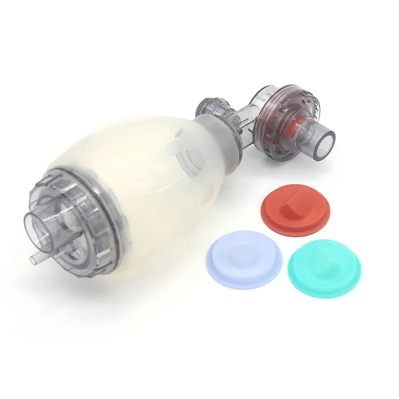
This calculation becomes more complex on multi-cavity tools, where uneven runner balance can cause one cavity to fill and pack out before the others, briefly spiking local pressure at the parting line near that cavity while the rest of the mold is still filling. Left unaddressed, this creates flash on some cavities while others produce clean parts from the same shot, a symptom that often gets misdiagnosed as a clamping tonnage problem when the root cause is actually runner imbalance. Mold flow simulation during the design phase, rather than trial-and-error adjustment on the production floor, is the more reliable way to catch this before the tool is cut.
Choosing the Right Mold Manufacturing Partner
The technical depth involved in cold runner balancing, vent sizing, and shear edge machining means that LSR mold design is not a task suited to generalist tooling shops. Selecting a manufacturing partner with dedicated LSR experience has a direct and measurable effect on first-pass yield and long-term tool durability.
Key Capabilities to Evaluate
When evaluating a potential mold partner, engineering teams should look beyond general tooling capability and assess experience specific to liquid silicone processing:
| Capability | Why It Matters |
|---|---|
| Mold flow simulation for LSR viscosity profiles | Predicts fill patterns and identifies vent locations before steel is cut |
| In-house DFM review for silicone-specific tolerances | Catches shrinkage and shear edge issues early, reducing rework |
| Class 7 or better cleanroom molding capability | Required for many medical and healthcare-adjacent applications |
| Experience with multi-cavity balanced runner design | Ensures consistent fill and cure across high-volume production tools |
| Post-cure and secondary process support | Confirms parts meet mechanical and biocompatibility specifications |
Prototyping to Mass Production Workflow
A structured path from prototype to production tooling reduces the risk of costly redesigns after a tool has already been cut. This typically follows a sequence of design validation through 3D printed or machined prototypes, a soft tooling or bridge tool run to confirm fit and function, mold flow simulation refinement based on real trial data, and finally the cutting of a production-grade hardened steel tool built to the cycle life required by the program. Partners with deep experience across this full workflow are generally better positioned to catch flash, venting, or runner balance issues before they become expensive production problems.
FAQ
How long does an LSR injection mold typically last in production?
A well-maintained LSR mold built from hardened tool steel can typically support anywhere from 500,000 to over 1 million cycles, depending on part geometry, cavity count, and how aggressively the shear edges and vents are exposed to wear during high-pressure fast-fill cycles.
What is the difference between LSR and standard silicone molding?
Standard silicone molding often refers to compression or transfer molding of high-consistency rubber (HCR), which is a gum-like solid requiring manual handling and longer cure times, while LSR is a pumpable two-part liquid that is metered, mixed, and injected automatically, allowing for tighter tolerances, higher repeatability, and shorter cycle times.
Can existing rubber molds be converted for LSR injection?
In most cases, molds designed for compression or transfer molding of solid rubber cannot be directly converted for LSR injection, since LSR’s low viscosity requires precision-machined vents, shear edges, and cold runner systems that solid rubber tooling was never designed to accommodate.